


50×40×9 m Open-Sided Steel Sports Canopy Preliminary Design
Preliminary Design
This page presents a public, watermarked preliminary design package for a 50.0 m × 40.0 m open-sided steel sports canopy concept with a 9.0 m height reference. The drawing set includes a general overview with the main dimensions, a roof plan, a structural layout, and interior and exterior rendering views.
The source material is marked preliminary design, so this page treats the drawings as design references for early sports-court and covered-venue planning rather than as final engineering documentation or as-built project photography. Browse more steel structure projects.
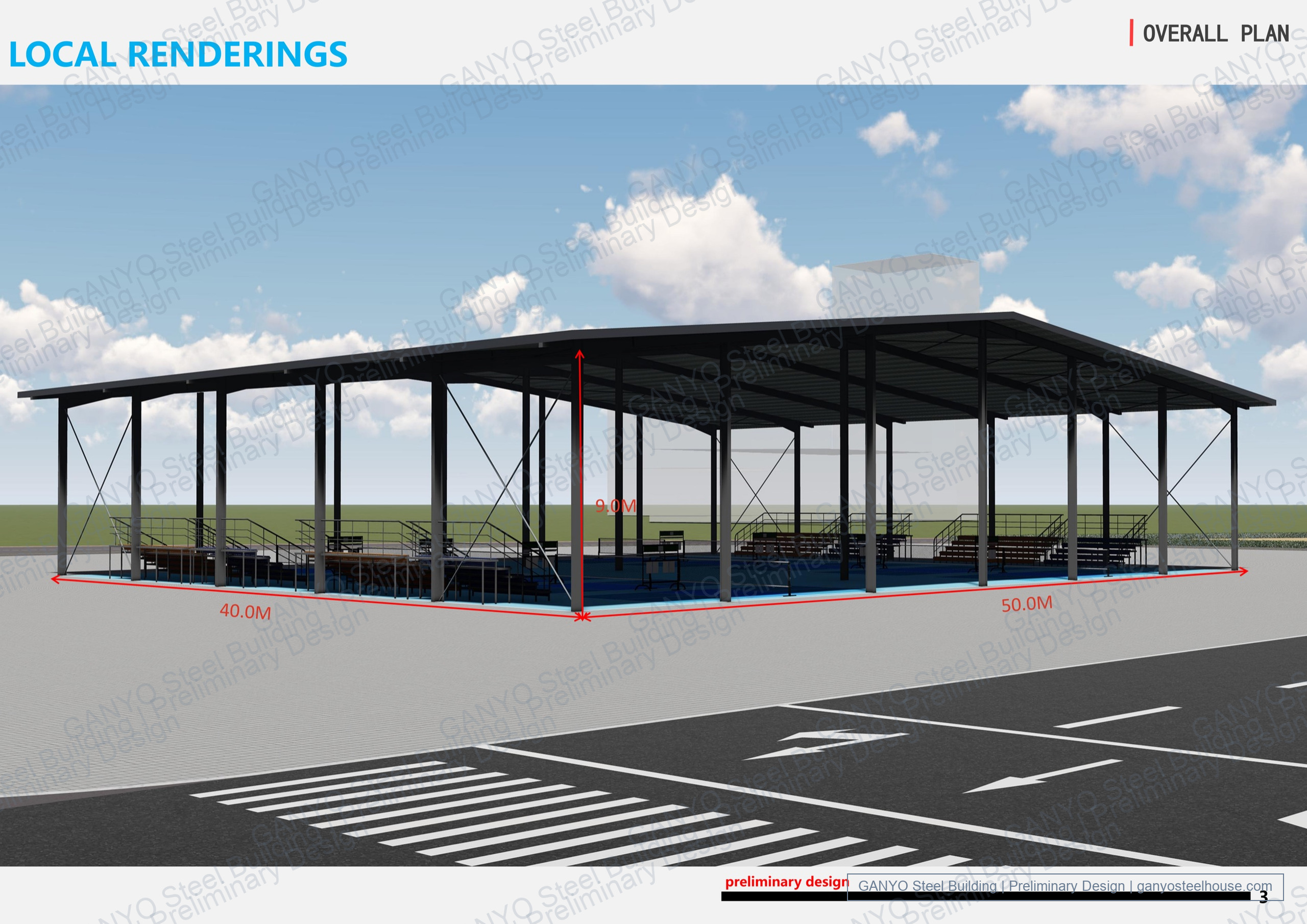
Structure Diagram & Dimensions
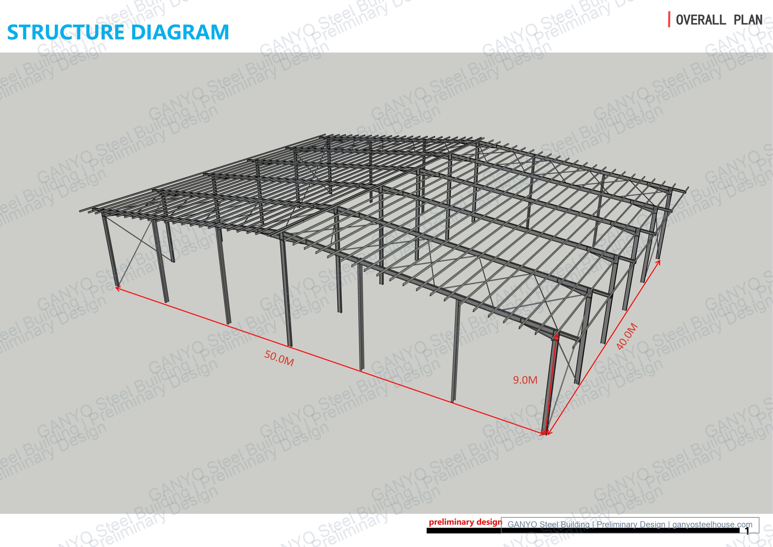
The visible design labels show a 50.0 m building length and a 40.0 m building width, giving a nominal footprint of approximately 2,000 m². A 9.0 m height annotation is shown as a height reference only — whether it represents the eave, the ridge or a clear height is not confirmed in the supplied boards.
The structure is open-sided rather than wall-clad. The visible steelwork includes columns, roof beams, purlins, profiled metal roof panels, X bracing in the end or side bays, and cross bracing in the roof plane. A central longitudinal column line appears in the renderings, suggesting the 40.0 m width is divided into two approximately 20.0 m spans; this is read from the visuals rather than a confirmed grid dimension.
Roof Plan
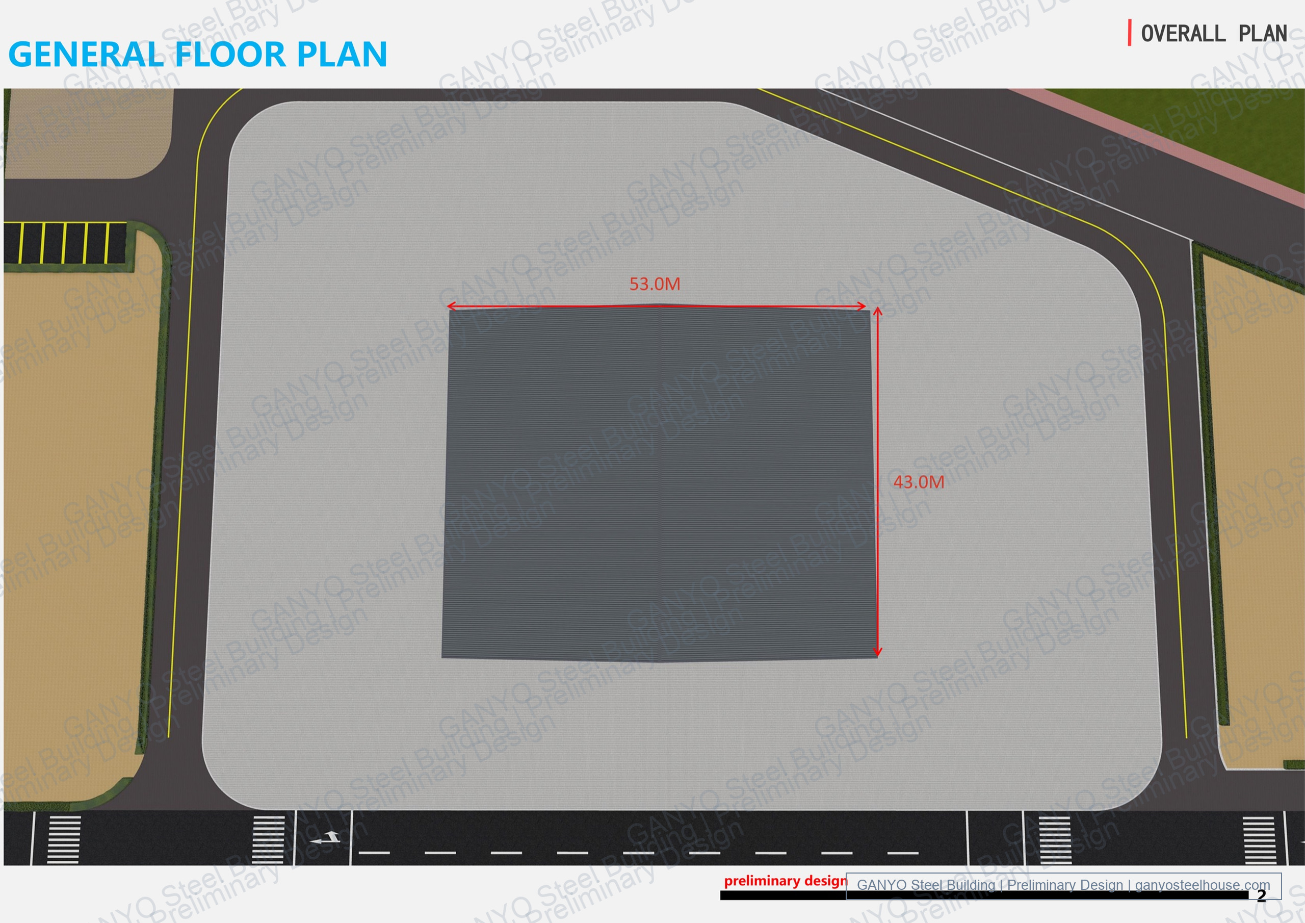
A separate roof plan shows a 53.0 m × 43.0 m roof projection — approximately 2,279 m² in plan — which is approximately 279 m² (about 14%) larger than the 50.0 m × 40.0 m footprint. If the roof projection is centred over the footprint, this implies roughly 1.5 m of horizontal overhang on each side. The roof is a low-pitch double-slope form with the ridge running along the 50 m direction; the roof pitch and the eave and ridge heights are not confirmed.
Concept Renderings
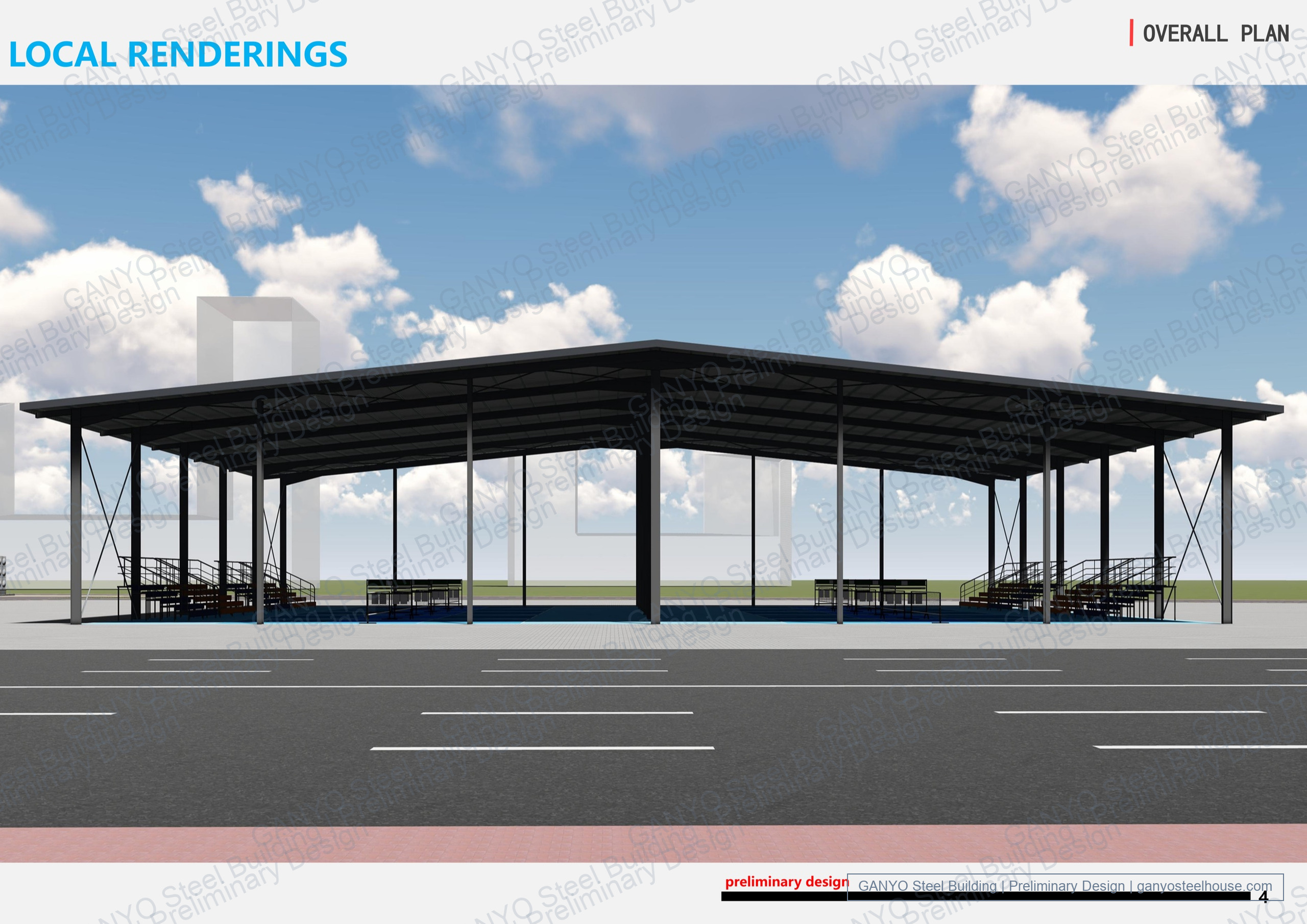
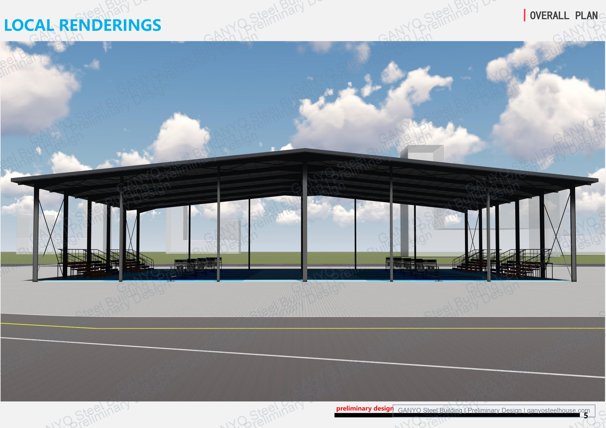
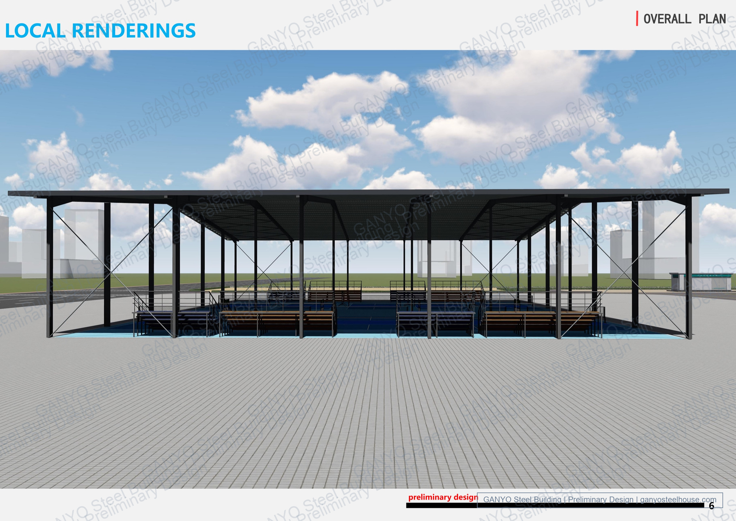
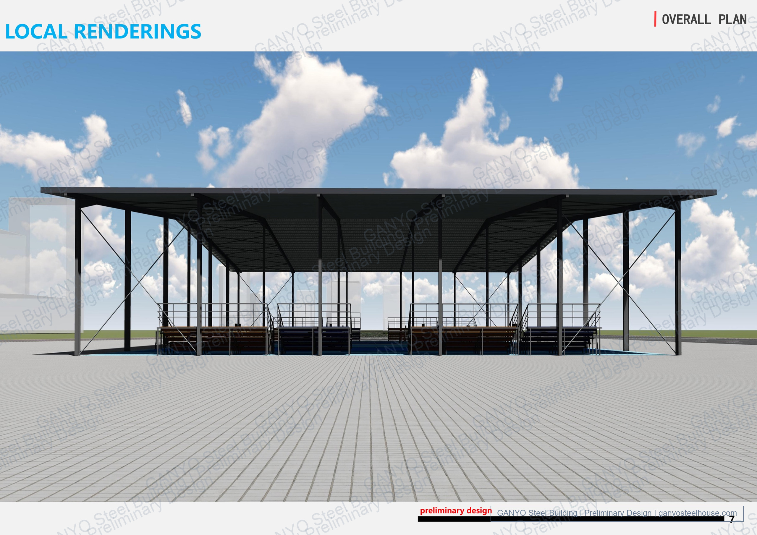
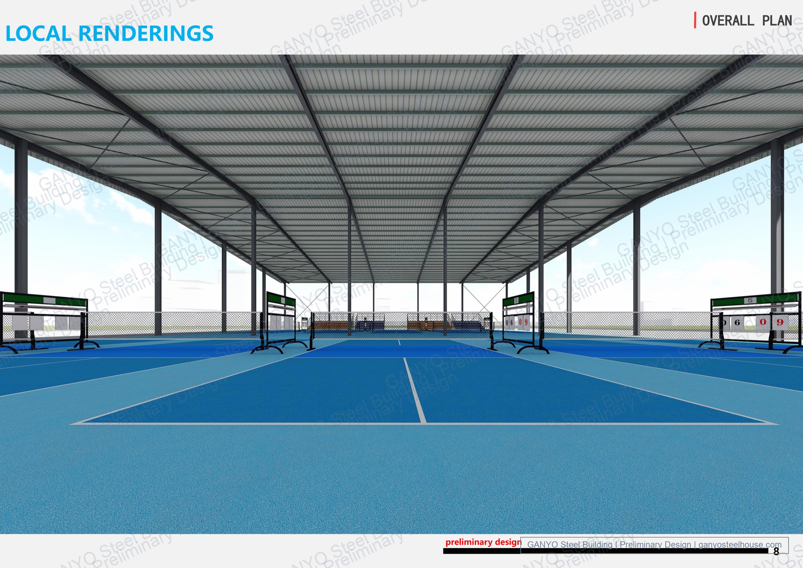
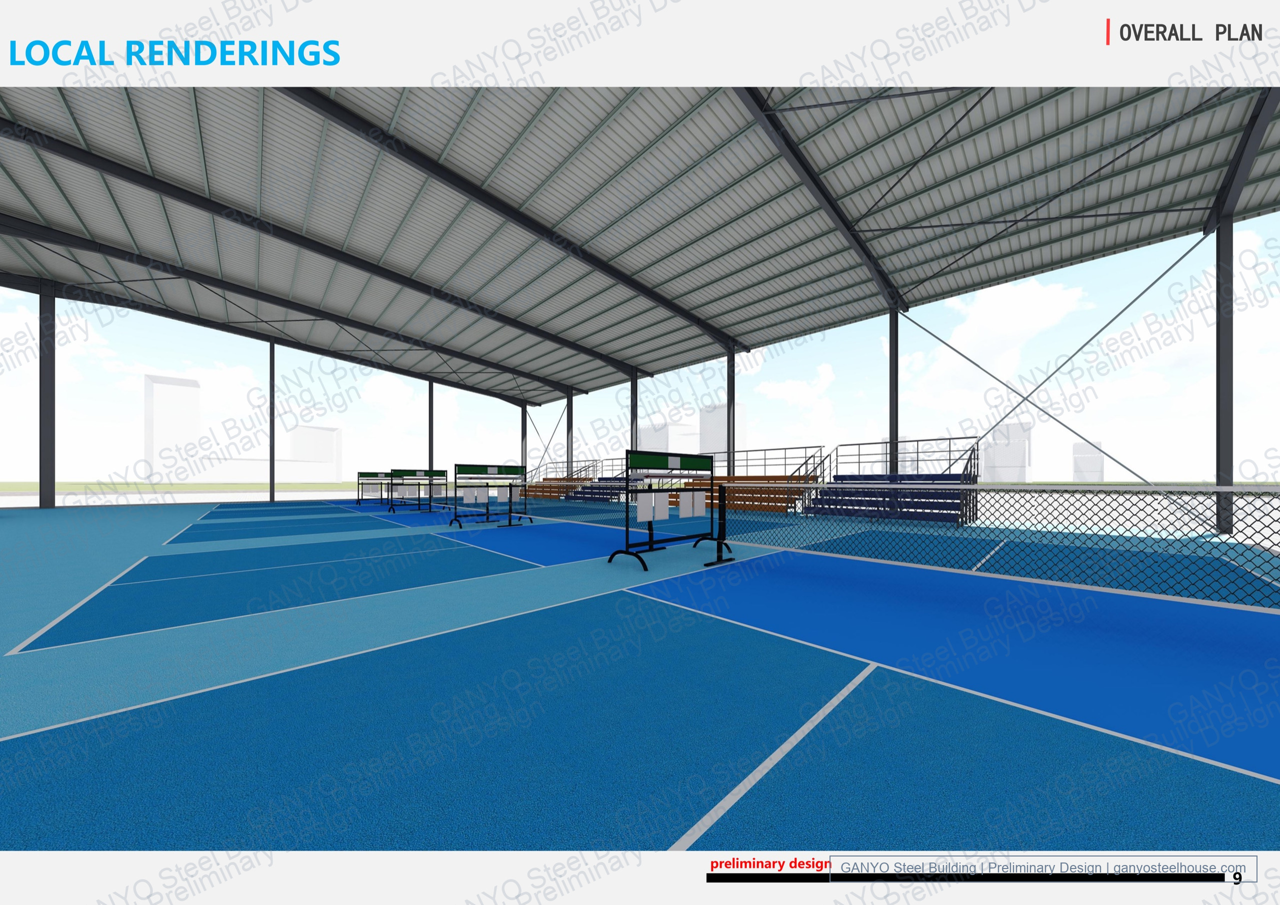
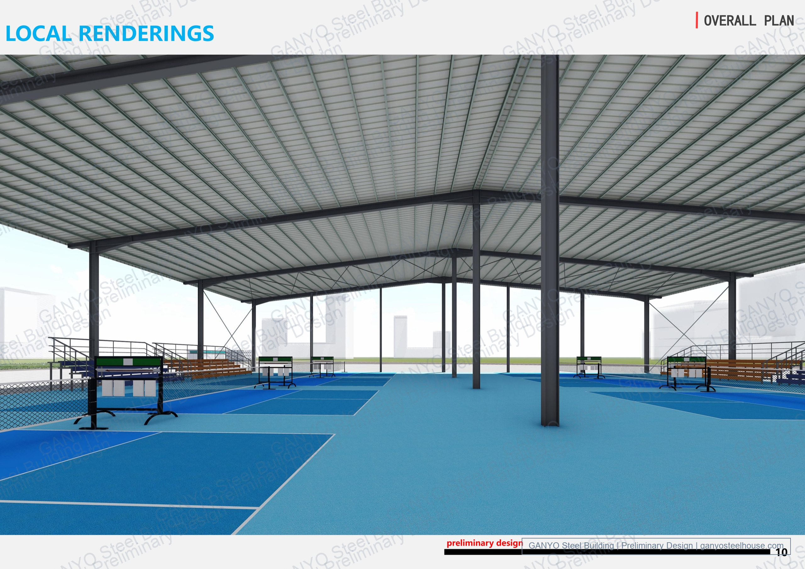
The renderings show the canopy covering multiple sports courts, with seating and surrounding netting visible inside. Because the sides are largely open, the canopy behaves as a covered court rather than an enclosed factory building. The exterior and interior views together provide supporting angles for the same preliminary scheme.
Installation Considerations
As a conceptual planning reference, several installation points follow from the visible scheme. A three-column-line layout — left, central and right — makes setting-out, anchor-bolt position and column-top level more critical, because a misaligned central line affects both roof spans and the continuous ridge line. The braced bays suggest a stable unit should be completed first, then extended along the 50 m length. The open sides make the partially erected canopy more sensitive to wind during installation, and the roof overhang adds eave finishing and waterproofing work.
These are planning observations, not an approved construction method statement. The final sequence depends on the full structural drawings, member sizes and weights, site access and crane selection.
Planning a Similar Steel Sports Canopy?
For a similar open-sided steel sports canopy or covered court, buyers should prepare the intended use, required width and length, height, roof overhang and drainage needs, seating and court requirements, site location, and any future expansion plans. For a large-span enclosed alternative, see the Steel Structure Warehouse product page. These inputs help the design and quotation process stay grounded in practical requirements.
Related
Plan Your Steel Sports Canopy
Share your required span, length, height, roof coverage, seating and court needs for an early design and quotation discussion.